Wind Tunnel Drag Study
I built a small open-jet wind tunnel and used it to compare how much drag four different shapes generate, then rebuilt each test in Ansys Fluent to see how well the simulation matched the physical setup. It's a hands-on look at the single idea that drove my Lockheed capstone: shape decides drag.
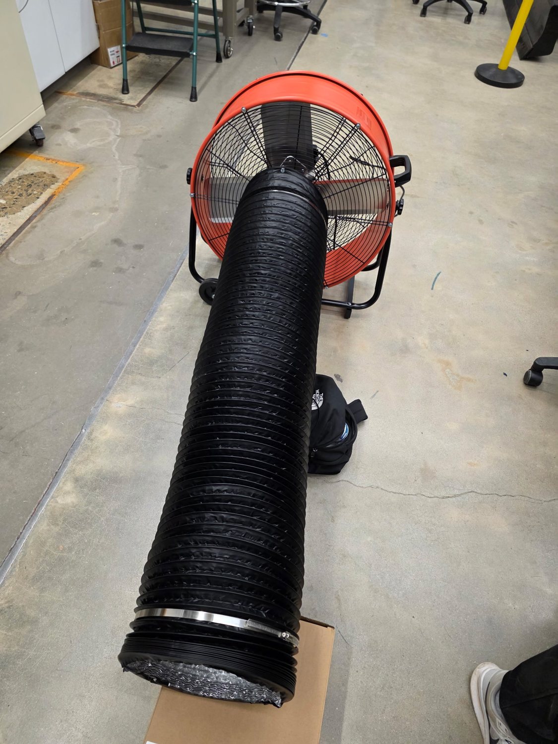
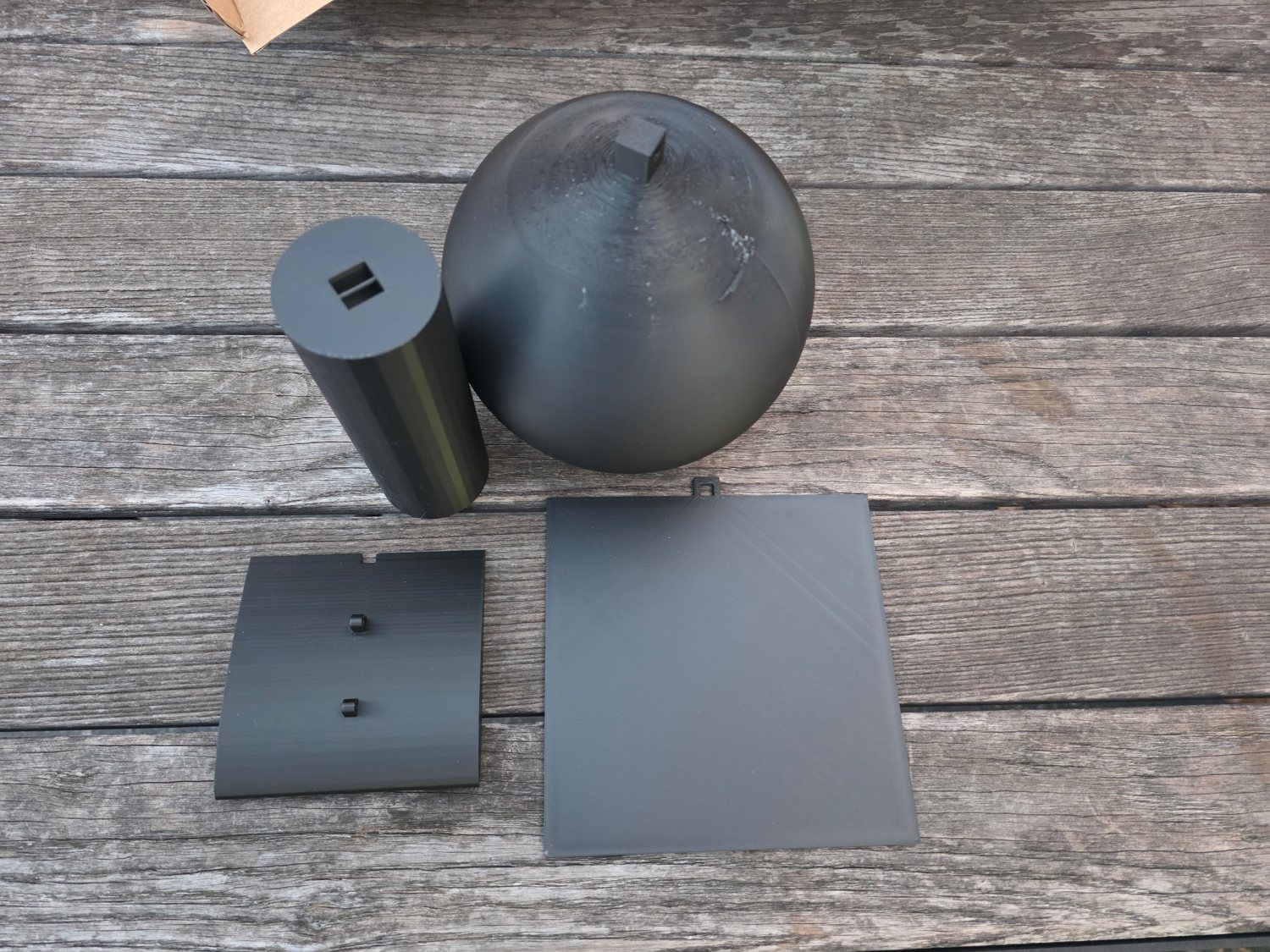
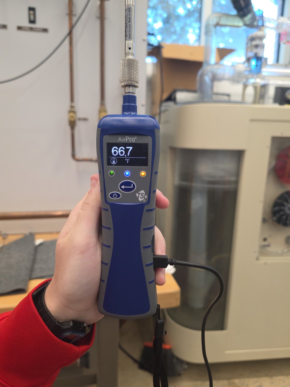
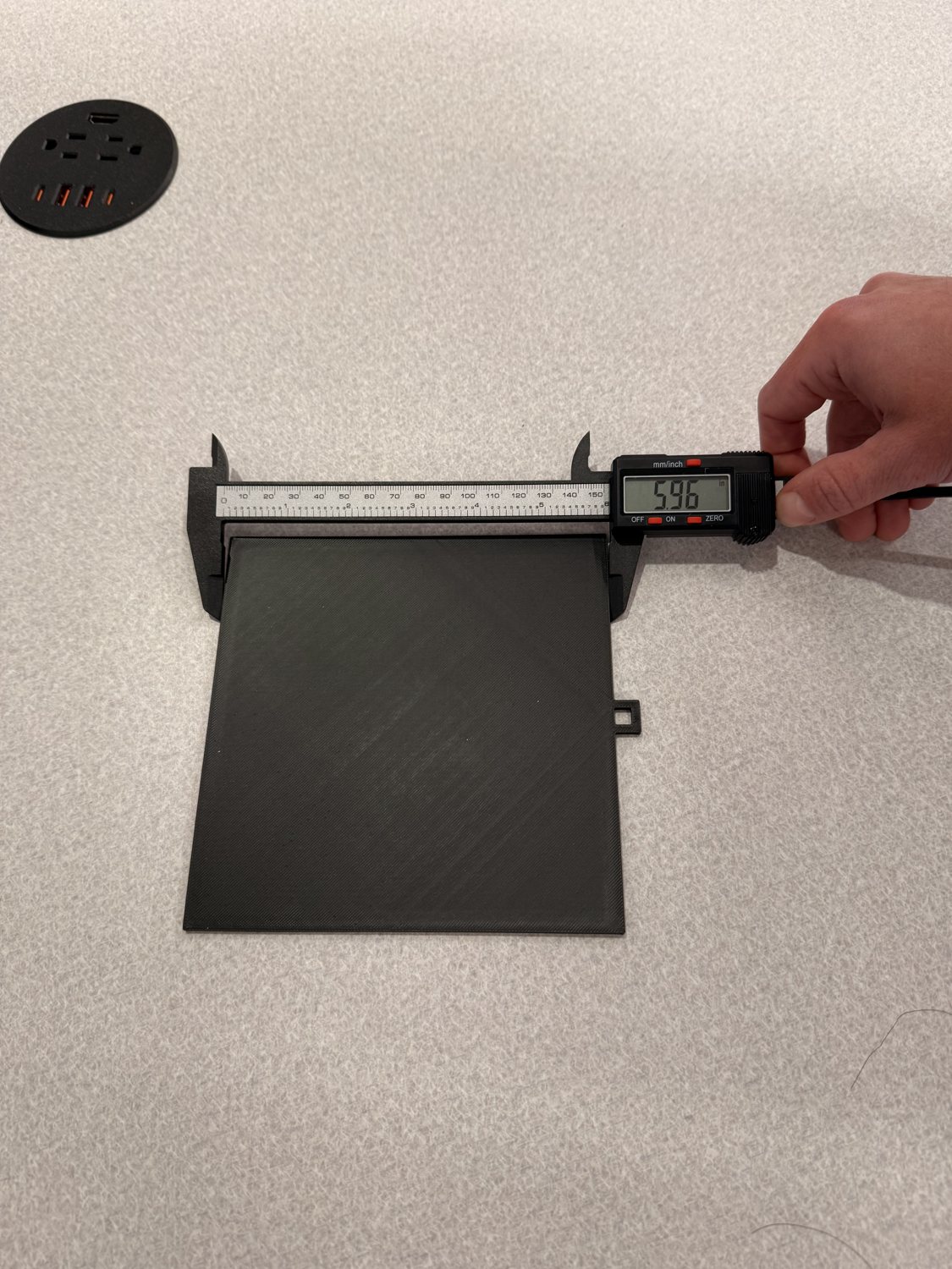
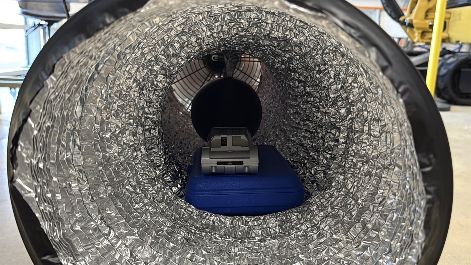
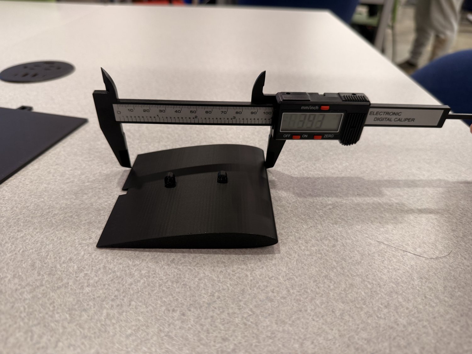
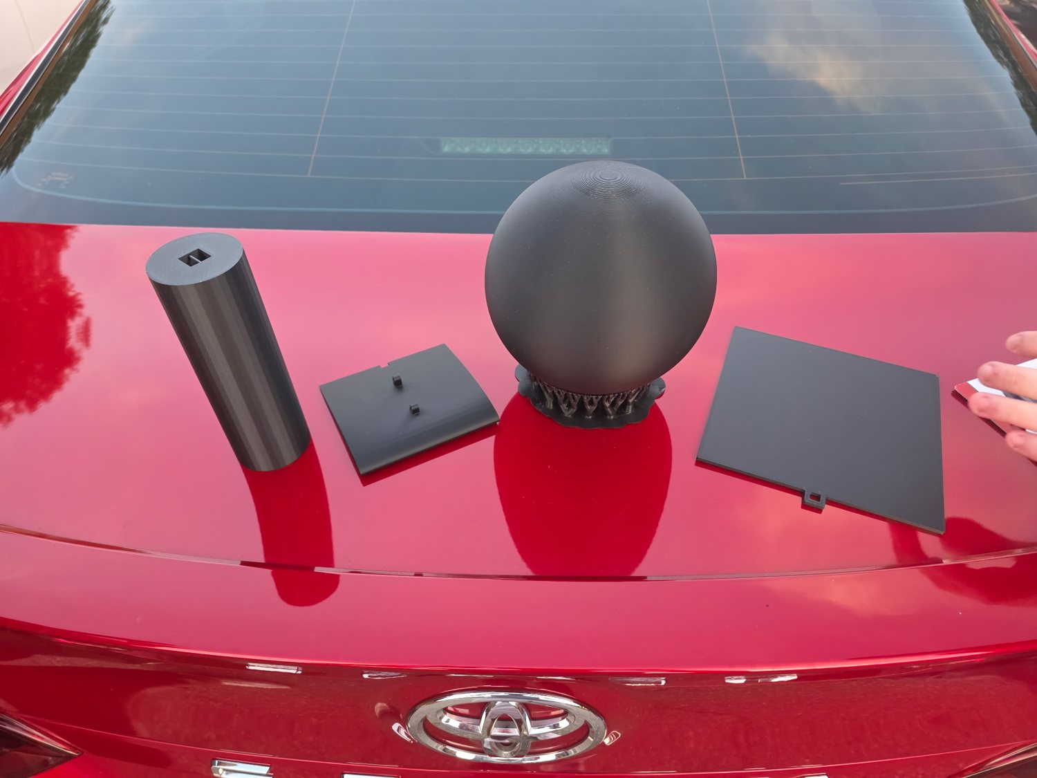
A high-flow drum fan feeds a ducted test section, with a handheld anemometer confirming the flow speed at the inlet. I 3D-printed four test bodies (a streamlined airfoil, a flat sheet, a cylinder, and a sphere), sized each with calipers, and mounted them one at a time in the flow. Each shape was run at two speeds, 3.97 ft/s and 7.12 ft/s.
For every shape and speed I ran a matching simulation and pulled the pressure field, velocity streamlines, velocity through the tunnel, and the net drag force on the body. The comparison views below line all four shapes up side by side.
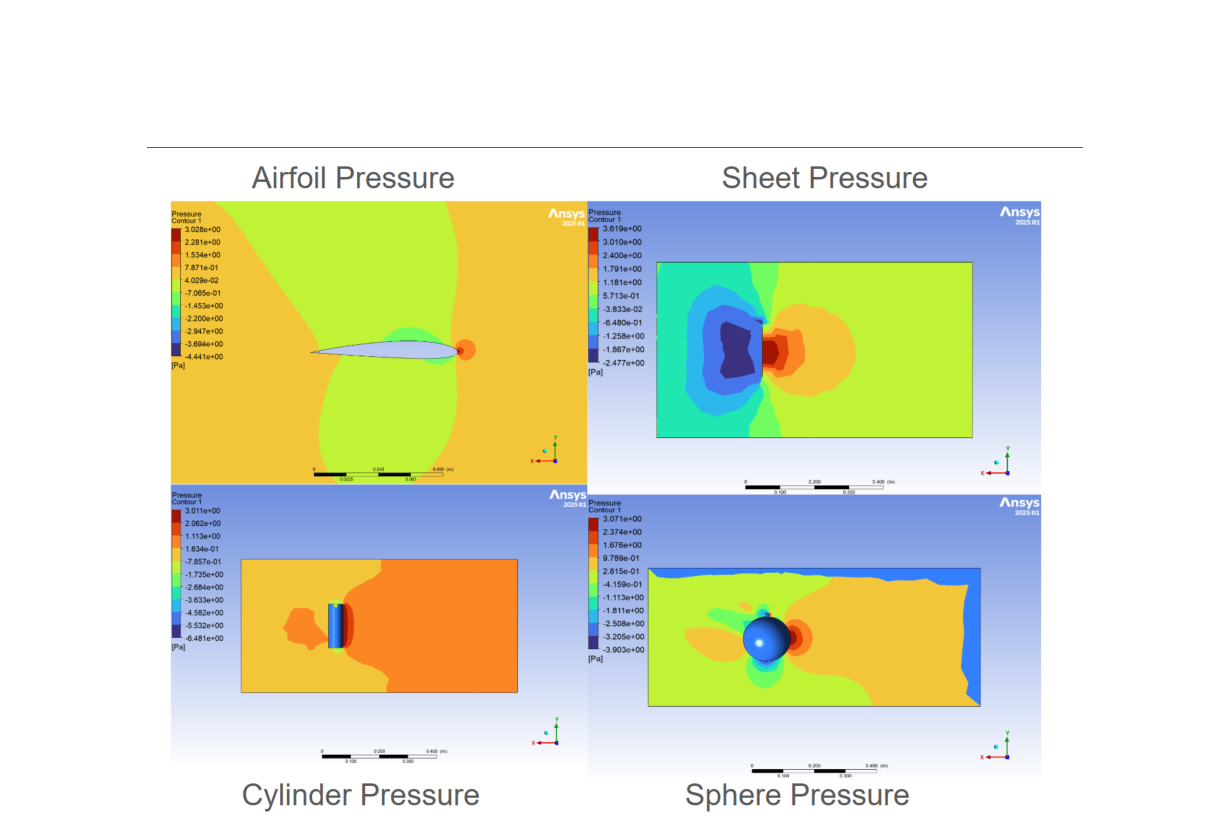
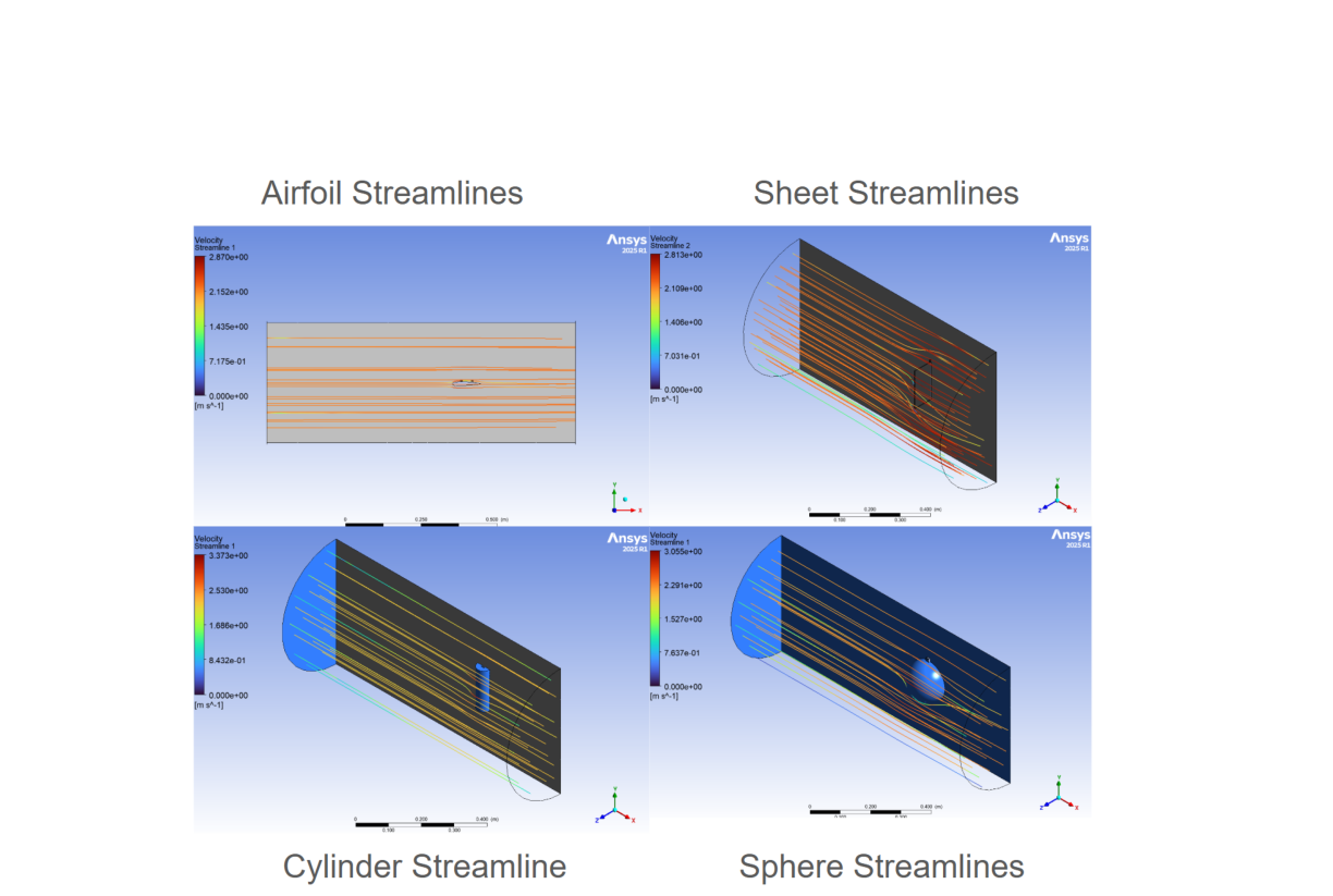
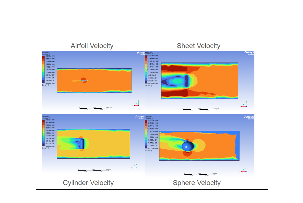
The numbers match the intuition from the plots. At both speeds the streamlined airfoil produced the least drag and the flat sheet the most, roughly 28 to 34 times more than the airfoil. Faster flow raised every shape's drag, as expected.
| Shape | Drag @ 3.97 ft/s | Drag @ 7.12 ft/s |
|---|---|---|
| Airfoil ★ lowest | 0.00062 N | 0.00167 N |
| Cylinder | 0.00170 N | 0.00509 N |
| Sphere | 0.00408 N | 0.01121 N |
| Flat sheet | 0.01761 N | 0.05630 N |
Same flow, same mounting, wildly different drag: the airfoil's attached flow and small wake beat the flat plate's massive separated wake by more than an order of magnitude. It's the physical, measurable version of exactly what the Lockheed capstone optimized for.