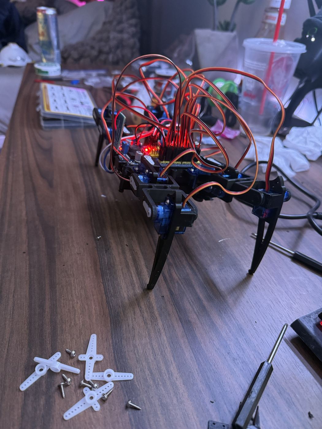
Autonomous Quadruped Robot
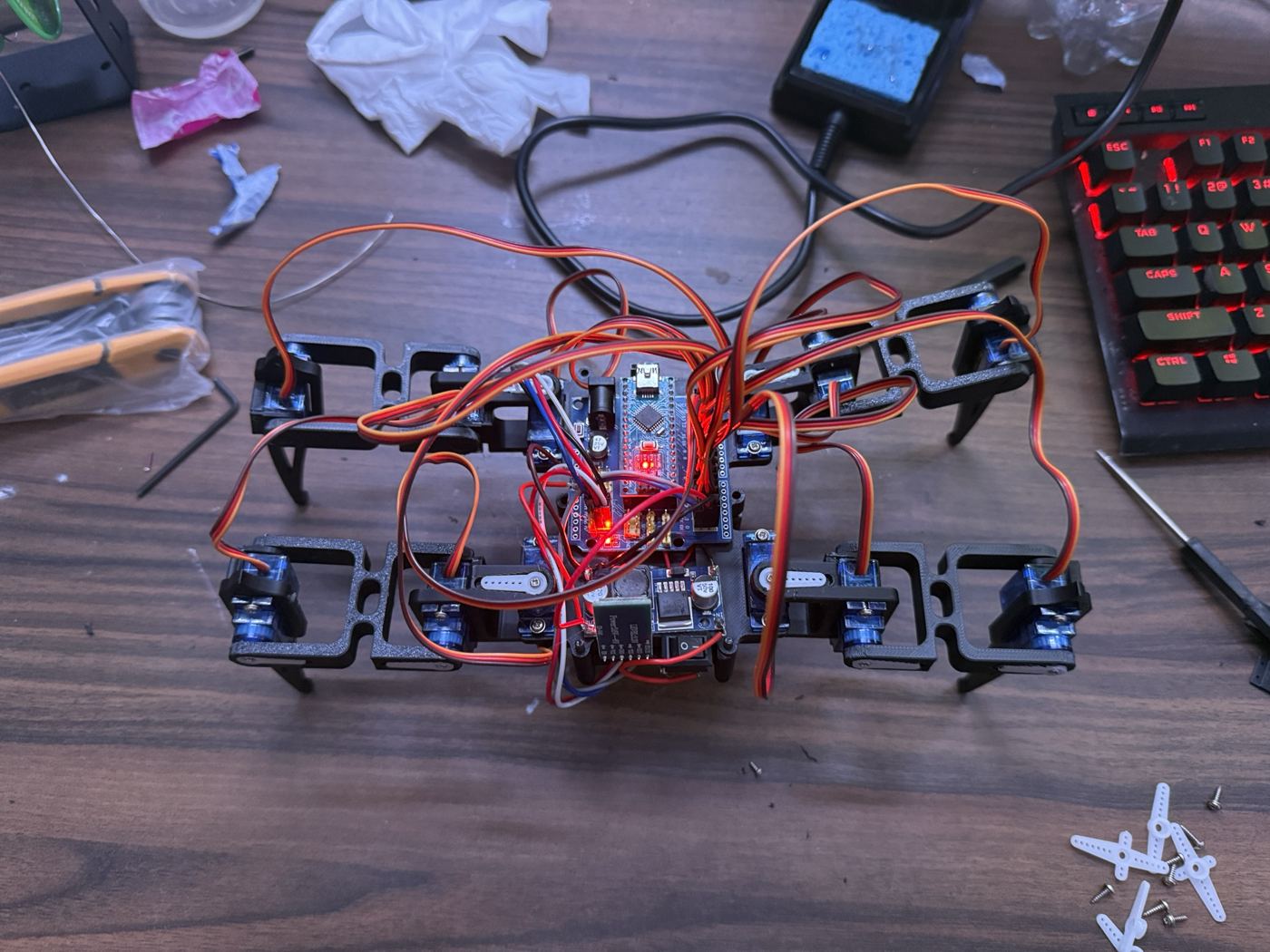
Nobody taught me how to do this. I had never soldered a joint or wired a power system before this build. I picked a 12-servo walking robot, ordered the parts, printed the frame on my own printer, and taught myself every skill it needed as I went. Five days later it was standing on its own legs.
Every structural part, the body, hip brackets, and curved legs, came off my Creality K2. Getting parts that hold a servo snug without cracking meant dialing in tolerances, wall thickness, and print orientation so the load runs along the layers instead of peeling them apart. This is where my 3D printing practice stopped being calibration prints and became real, load-bearing parts.
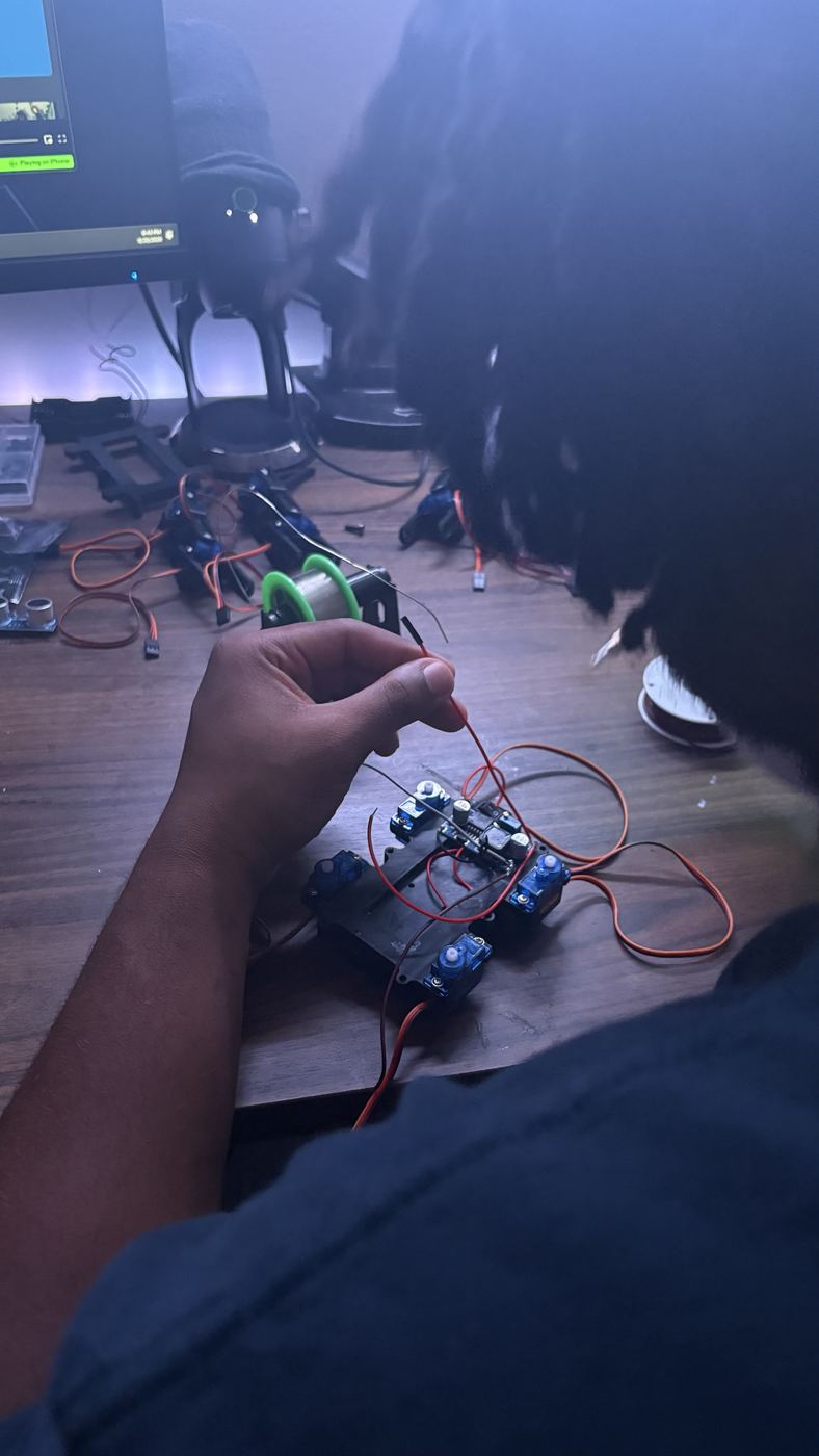
The power system is hand-soldered. Two 18650 lithium cells feed an LM2596 buck converter, which I tuned down to a steady 5V for the servo rail so twelve motors can pull current at once without browning out the microcontroller. I learned tinning, clean joints, heat control, and polarity the hard way, with a multimeter on every connection before power ever touched the board.
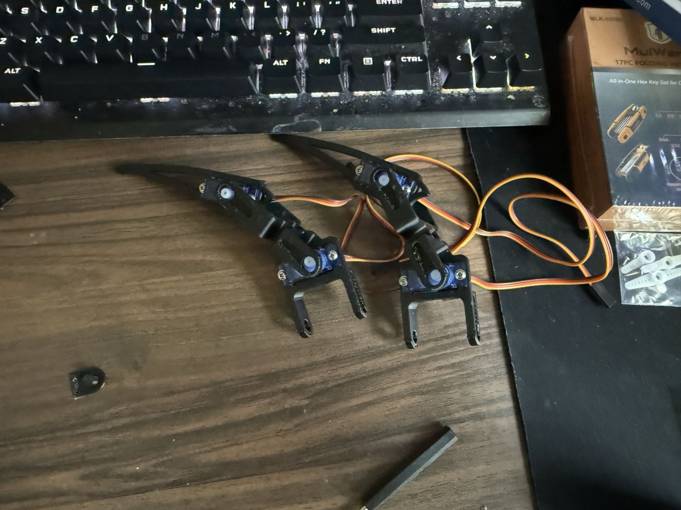
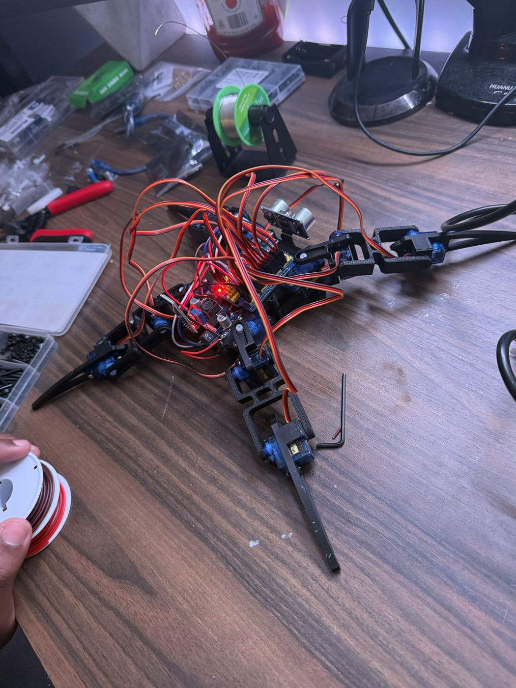
The Arduino Nano sits on a sensor shield that breaks out a signal, power, and ground pin for each of the 12 servos, plus an HC-SR04 ultrasonic sensor up front and a Bluetooth module on the serial lines. Before attaching any horn I centered every servo in software, then mounted the legs at known angles so the gait code starts from a true neutral stance. Getting the board to upload meant troubleshooting a CH340 clone chip, the right processor setting, and pulling the Bluetooth module off the RX/TX lines during flashing.
| Skill | What I learned on this build |
|---|---|
| Soldering | Tinning, heat control, clean joints, strain relief, checking every joint with a multimeter |
| Power electronics | Li-ion cells, buck converter voltage tuning, current draw of 12 servos, avoiding brownouts |
| Embedded firmware | Arduino IDE (C++), board and port setup, servo libraries, serial and BLE communication |
| Mechanisms | Servo centering, horn indexing, leg kinematics and a neutral stance for the gait |
| 3D printing | Load-bearing parts, tolerances for press-fit servos, orientation for strength |
| Troubleshooting | Driver issues on a clone board, upload conflicts, wiring faults, isolating one variable at a time |
This is the same loop I want to bring to the field: read the drawing, build it with my hands, measure it, and fix what doesn't match. I didn't wait for a class to teach me soldering or electronics. I needed them, so I learned them, and the robot is the proof.
A custom Bluetooth control app and a handheld remote built around a second BLE module, then an ESP32-based quadruped and a 3D-printed SMARS rover.