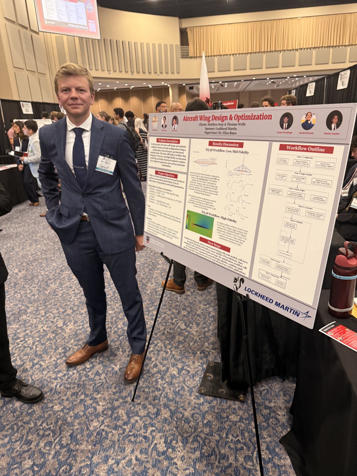
Aircraft Wing Design & Optimization
Over the 2025 to 2026 academic year, our six-person, Lockheed Martin-sponsored team built a full aerodynamic wing-optimization workflow and used it to redesign a wing for the XQ-58A Valkyrie. The goal was a wing that produces the same lift for less drag, using the same mix of fast and high-accuracy tools that real aerospace teams rely on.
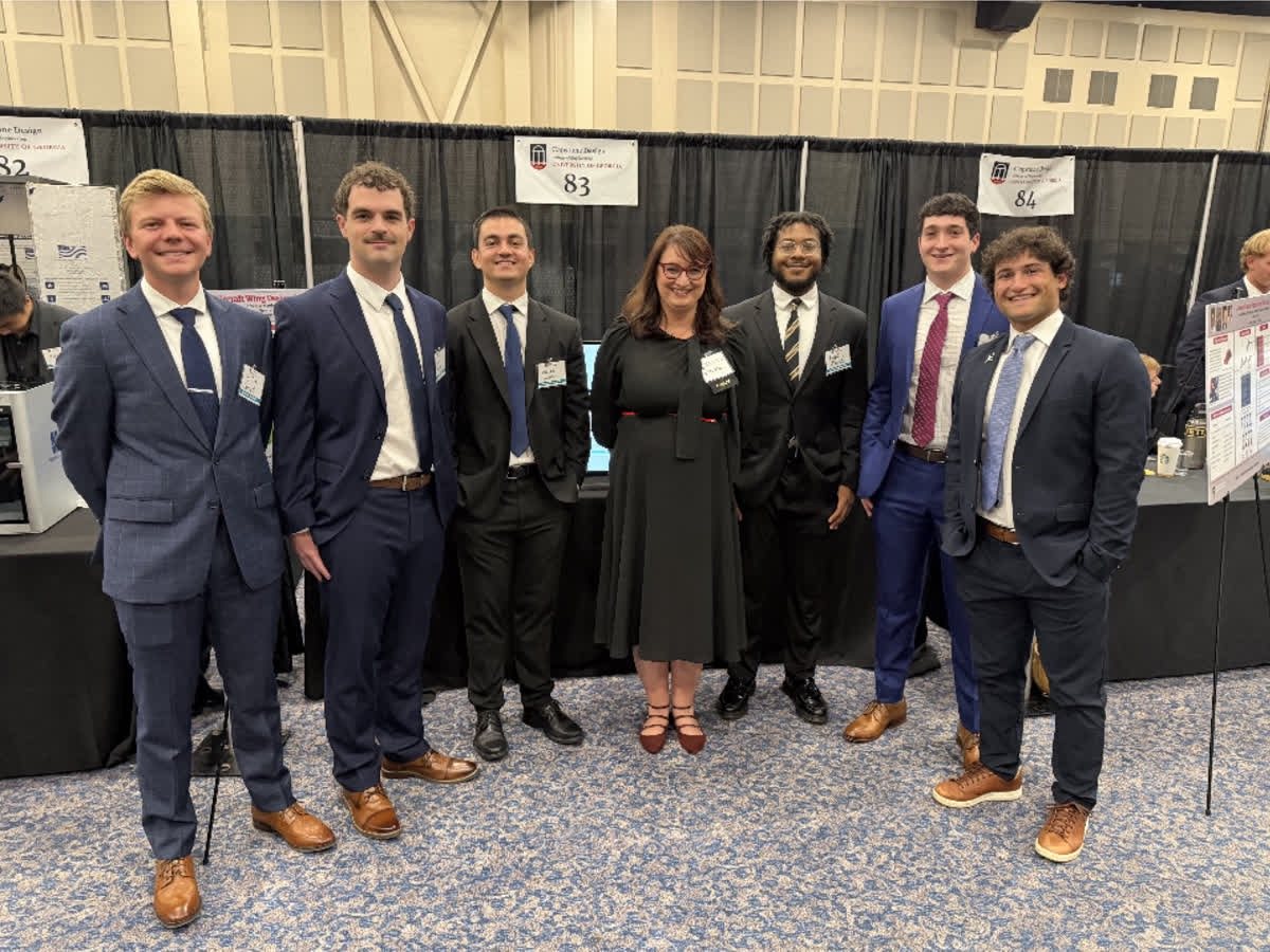
Team: Griffin Cantrell · Edwin Harper · Garrett Kuhn · Cooper Mendlinger · Randal Richards · Martin Vassilev · Supervisor Dr. Banu
Meet the aircraft: XQ-58A Valkyrie
The Valkyrie is a stealthy, low-cost "loyal wingman" drone built by Kratos to fly alongside crewed fighters like the F-22 and F-35. It has no landing gear: it launches off a rail with a rocket booster and comes down by parachute, so it needs no runway. A more efficient wing means more range and endurance for the same fuel, which is exactly what our project targeted.
A wing's shape decides how much drag the aircraft fights at cruise. Finding the best shape means testing thousands of options, but the accurate analysis (CFD) is far too slow to run on all of them, and the fast analysis is too rough to trust on its own. The real skill is combining the two: screen fast, then verify slow. Our task was to build that combined workflow end to end and prove it on a Valkyrie wing.
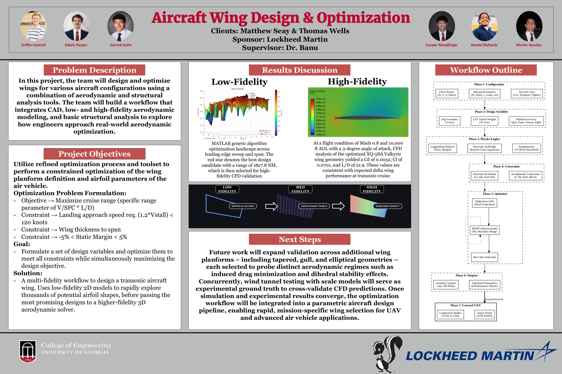
The optimizer's job was to maximize cruise range (a specific-range measure, V/SFC × L/D) while respecting real design limits: a landing approach speed (1.2 × Vstall) under 120 knots, a bounded wing thickness-to-span ratio, and a static margin held between −5% and +5% so the aircraft stays controllable.
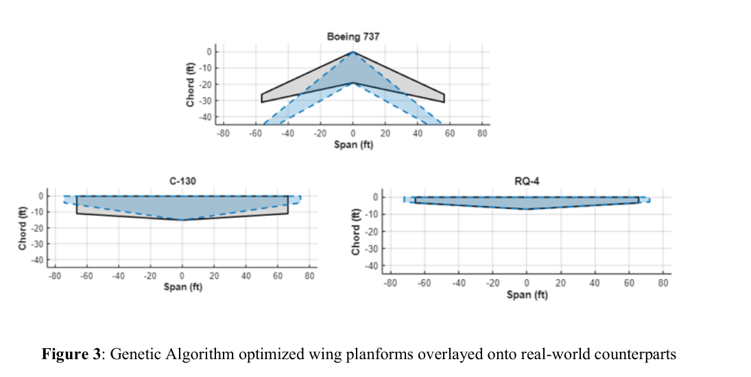
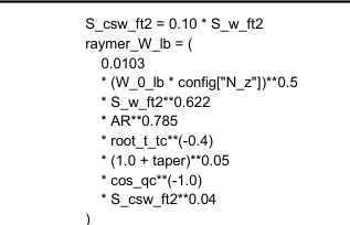
We ran it as a loop that moves from cheap-and-fast to expensive-and-accurate, feeding what we learned back into the next round of shapes. A genetic algorithm searches broadly, then a gradient-based optimizer (IPOPT) fine-tunes a 39-variable design, with Raymer weight estimates keeping the result physically honest.
I helped build the pipeline end to end: setting up parametric wing geometry, running the low-order sweeps (AVL and AeroSandbox's vortex-lattice + NeuralFoil) to screen planforms and airfoils quickly, then taking the best candidates into high-fidelity CFD in Ansys Fluent to validate and refine them. I used MATLAB, Python, and Raymer's sizing methods for the weight and performance estimates that keep the design honest. The target throughout: minimize drag at a set 1g cruise lift while holding the mission and structural limits.
These are actual outputs of the optimizer: the wing planform it converged on, the root and tip airfoil sections it shaped, the same method applied to real aircraft to check it generalizes, and a piece of the weight math underneath it all.
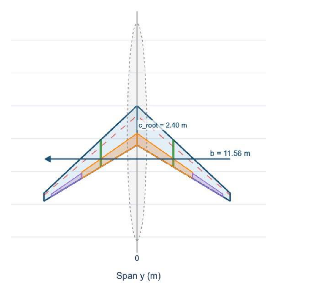

At a transonic cruise condition (Mach 0.8, 10,000 ft AGL, 3° angle of attack), high-fidelity CFD of the optimized XQ-58A wing returned a lift-to-drag ratio of 21.9, with Cd = 0.0032 and Cl = 0.0701, consistent with expected delta-wing performance. The low-fidelity search flagged this design first, its best candidate reaching a range of 1,827.8 NM, which we then confirmed in CFD.
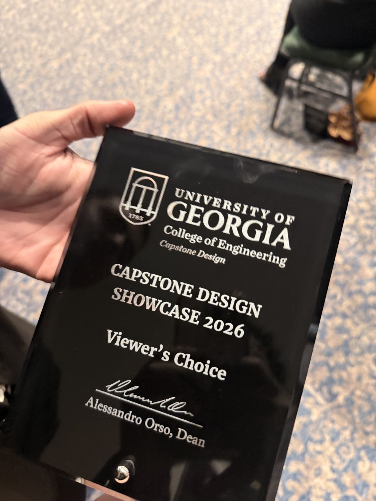
We delivered a complete, documented wing-optimization workflow, from inputs to geometry to multi-fidelity analysis to a validated design, written up so it can be reused on other aircraft. At the UGA Capstone Design Showcase, the project won the Viewer's Choice Award, voted by the public across every engineering discipline. The full report, poster, and code are linked below.